Start with width and height
Width and Height drive the plate outline, the hole layout, and the generated data.
Stop redrawing plate geometry and recalculating hole spacing every time the dimensions change.
Change width or height and the plate outline, hole count, spacing, and output data update automatically. LogiDraft applies rule-driven geometry so the drawing and generated data stay in sync.
Change width and watch hole count and spacing recalculate instantly.
This geometry is generated directly from the same logic used in the workspace.
Change width and the layout updates automatically.
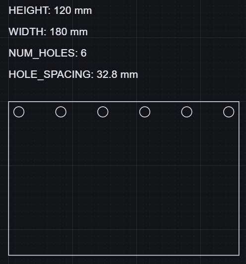
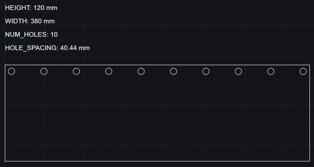
Increasing width steps hole count from 6 to 10 and recalculates spacing automatically.
Change inputs in the workspace and this result updates automatically.
These changes are reflected directly in structured output data.
| Width (mm) | Height (mm) | Hole Count | Hole Spacing (mm) |
|---|---|---|---|
| 180 | 120 | 6 | 32.8 |
| 380 | 120 | 10 | 40.44 |
Geometry and data stay aligned because they are generated from the same logic.
Width and Height resolve the plate geometry and the reported results together.
A lookup table maps width to hole count, and the spacing calculation is encoded directly in the model.
Width and Height drive the plate outline, the hole layout, and the generated data.
Width resolves between 80 and 480. Height resolves between 40 and 240 before geometry is drawn.
A width-based lookup table selects the hole count. At 180 mm width, the resolved hole count is 6.
Once width and hole count are resolved, spacing is calculated across the usable span automatically. At 180 mm width, spacing resolves to 32.8 mm.
Hole count is not hard-coded into the geometry. The example reads a width-based lookup table and selects the appropriate quantity for the resolved width.
| Max width | Hole count |
|---|---|
| 160 and below | 4 |
| 240 and below | 6 |
| 320 and below | 8 |
| 400 and below | 10 |
| 480 and below | 12 |
After width is clamped, the usable span is the plate width minus 16 mm. Hole spacing is then calculated by dividing that span across the resolved hole count.
That means the automatic hole spacing always reflects the current geometry and the current hole quantity. The plate stays consistent without manual recalculation.
The resolved plate produces usable engineering data that stays aligned with the geometry and can be exported directly.
Width, height, hole count, and hole spacing are available as generated data from the same evaluated model that draws the plate.
Exported data stays aligned with the visible result, so downstream schedules, validation, or reporting can use the same resolved values.
| Sheet | MAIN |
|---|---|
| Definition | Mounting Plate |
| Height (mm) | 120 |
| Hole Count | 6 |
| Hole Spacing (mm) | 32.8 |
| Width (mm) | 180 |
A mounting plate shows the difference between geometry-only drafting and a rule-driven system that keeps geometry and data aligned.
Open this and change one value - you'll immediately see how the system works.
Open this example and:
How to use values to control geometry.
How inputs drive geometry and outputs from one model.
Another practical system driven by changing inputs.
Exact directive properties and commands.