Inputs
- Incoming Voltage
- Control Voltage
- Control Load
Stop resizing control power sections and redrawing transformer groups every time the load changes.
Change load or voltage and the system updates transformer groups, fuse selection, layout, and generated data automatically. LogiDraft applies rule-driven logic so the drawing and data stay in sync.
Change control load and watch transformer groups and fuse sizing update instantly.
This layout is generated directly from the same logic used in the workspace.
Change load or voltage and the layout updates automatically.
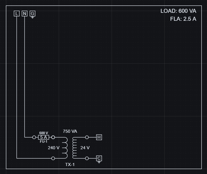
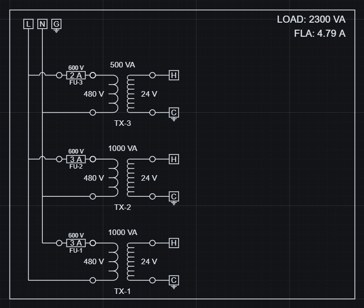
Increasing load adds transformer groups and scales fuse protection automatically.
Change inputs in the workspace and this result updates automatically.
These changes are reflected directly in structured output data.
| Load (VA) | Transformer Groups | Total Transformer VA |
|---|---|---|
| 600 | 1 | 750 |
| 2300 | 3 | 2500 |
Geometry and data stay aligned because they are generated from the same logic.
Control load and voltage resolve the transformer selection, fuse sizing, and schematic output together.
The sizing logic follows lookup tables and threshold rules encoded directly in the model.
The first transformer group covers the first 1000 VA of control load. Additional groups stay inactive until the load crosses the next threshold.
That means the example scales from one transformer group to two and then three without redrawing the schematic. Incoming voltage also changes fuse selection because the lookup table is keyed by both VA and voltage.
The resolved panel produces usable engineering data that can be exported and kept aligned with the schematic.
Electrical role, part selection, voltages, transformer VA, and fuse current come from the same resolved logic that drives the layout.
Exported data stays aligned with the evaluated design, so schedules and reporting use the same resolved values.
| Tag | Component | Role | Part Key | Resolved values |
|---|---|---|---|---|
| TX-1 | Control Transformer | Distribution | TX-240-24-100 | 240 to 24, 100 VA |
| FU-1 | Fuse | Protection | FUSE-1A-250 | 250 V, 1 A |
| H | Terminal Block | Distribution | TB-300 | 300 V |
| C | Terminal Block | Distribution | TBG-600 | 600 V, grounding |
Control power design is a recurring task. The same rules that choose components can also keep the schematic and the generated data consistent.
Open this and change one value - you'll immediately see how the system works.
Open this example and:
This example is part of a larger configurable control panel pattern: inputs resolve sizing logic, schematic geometry, and BOM output together.
See how control power, motor starters, panel outputs, reusable assemblies, and BOM coordination fit into one workflow.
Read the workflow guideLearn where LogiDraft fits for repeatable schematic systems driven by inputs, lookup tables, and reusable logic.
Read the schematic guideHow to use the workspace to change live inputs.
How resolved inputs become generated results.
A focused practical sizing system.
Exact output behavior for generated data.