Inputs
- Motor HP values
- Motor count
- Motor voltage
- Control type
- Run-light inclusion
Stop rebuilding panel layouts and rechecking totals every time motor requirements change.
Change motor count, horsepower, or voltage and the starter assemblies, control power, panel totals, and output data update automatically. LogiDraft composes reusable rule-driven assemblies so the full panel and data stay aligned.
Change motor count or voltage and watch starters, control power, and total FLA update instantly.
This panel is generated directly from the same logic used in the workspace.
Change motor quantity or motor data and the panel updates automatically.

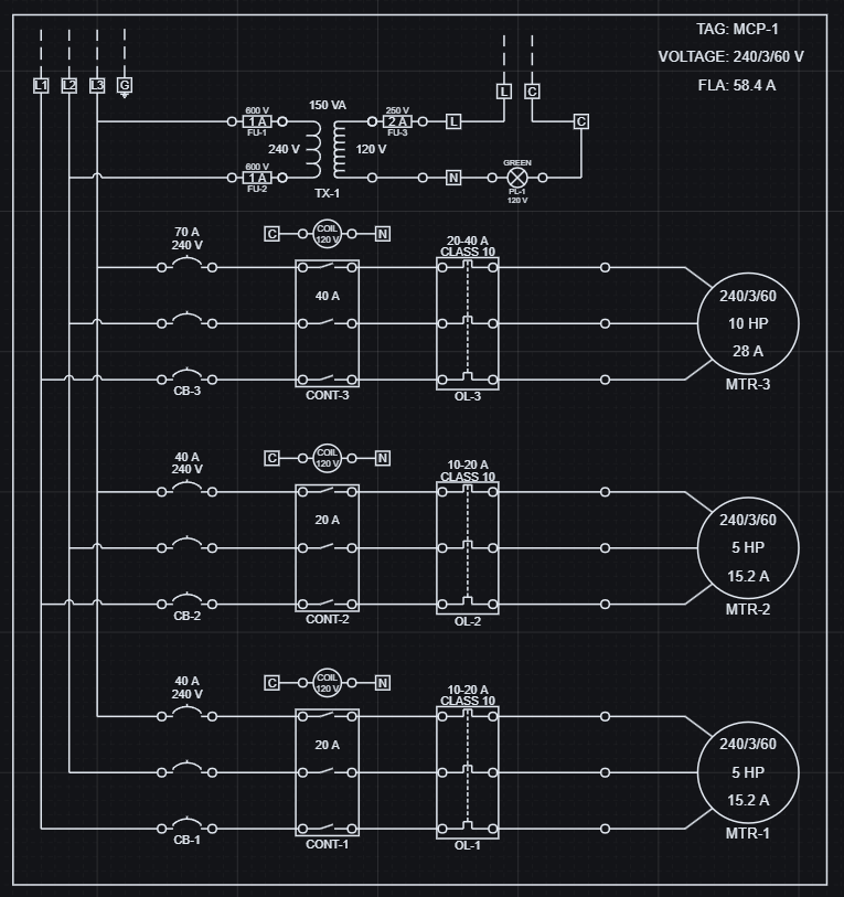
Increasing motor count and changing voltage updates starters, protection, control power, and total FLA together.
Change inputs in the workspace and this result updates automatically.
These changes are reflected directly in structured output data.
| Configuration | Voltage | Motor Count | Total FLA |
|---|---|---|---|
| 2 motors | 480 V | 2 | 12.4 A |
| 3 motors | 240 V | 3 | 58.4 A |
Geometry and data stay aligned because they are generated from the same logic.
A small set of panel inputs resolves the starter assemblies, control power, and reported outputs together.
Reusable assemblies are coordinated by shared parameters encoded directly in the model.
Total FLA is calculated by summing the FLC of the active motors, and control power steps from 30 to 60 to 90 VA as motor quantity increases from 1 to 3.
The current sample panel resolves to 2 motors at 240 V with 37.2 A total FLA and 60 VA of control power.
Panel scaling is reflected directly in the resolved output values.
| Configuration | Motor set | Total FLA | Control power |
|---|---|---|---|
| 1 motor | 5 HP @ 240 V | 15.2 A | 30 VA |
| 2 motors | 5 HP + 7.5 HP @ 240 V | 37.2 A | 60 VA |
| 3 motors | 5 HP + 7.5 HP + 5 HP @ 240 V | 52.4 A | 90 VA |
The resolved panel produces usable engineering data that can be exported and kept aligned with the visible system.
Component selections, electrical roles, and panel totals are available as generated data from the same evaluated panel.
Exported data stays aligned with the layout, so BOMs and downstream reporting use the same resolved values as the drawing.
Generated data can be exported as CSV or JSON.
| Part Key | Component | Role | Resolved meaning |
|---|---|---|---|
| MTR-5HP-240-3 | Motor | Load | 5 HP motor instance |
| CONT-20A-CV24 | Contactor | Control | 20 A contactor with 24 V coil |
| CB-40A-3P-240 | Circuit Breaker | Protection | 40 A, 3-pole breaker |
| TX-240-24-60-UL | Control Transformer | Distribution | 60 VA control power transformer |
Panel design is about keeping a whole electrical system coordinated as requirements change.
Open this and change one value - you'll immediately see how the system works.
Open this example and:
This full panel example shows nested assemblies, reusable starter logic, control power, protection, and structured outputs working as one evaluated system.
Learn how configurable panel workflows connect control power, starters, schematics, reusable blocks, and BOM coordination.
Read the panel workflow guideSee how BOM-style rows can come from the same evaluated panel instances that drive the drawing.
Read the BOM guideHow to use nested block assemblies.
How nested systems combine into larger assemblies.
A focused practical system inside the same design family.
Exact fields for placed block instances.