Inputs
- Motor HP
- Line voltage
- Coil voltage
Input motor horsepower and voltage to automatically generate a coordinated motor starter.
Enter inputs to automatically resolve FLC, breaker, contactor, overload, and generated data.
This starter is generated directly from the same logic used in the workspace.
Change horsepower or voltage and the starter updates automatically.
Increasing motor size updates breaker, contactor, overload, and motor data together.
These changes are reflected directly in structured output data.
| Motor | FLC (A) | Breaker (A) | Contactor (A) | Overload Range (A) |
|---|---|---|---|---|
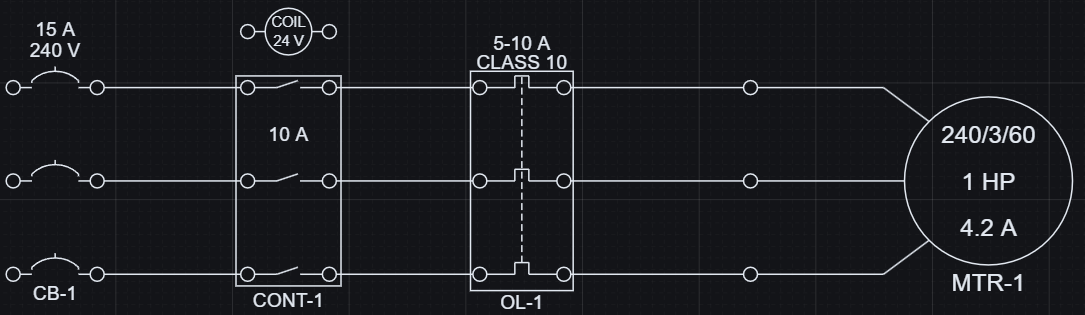
| 1 HP @ 240 V | 4.2 | 15 | 10 | 5-10 |
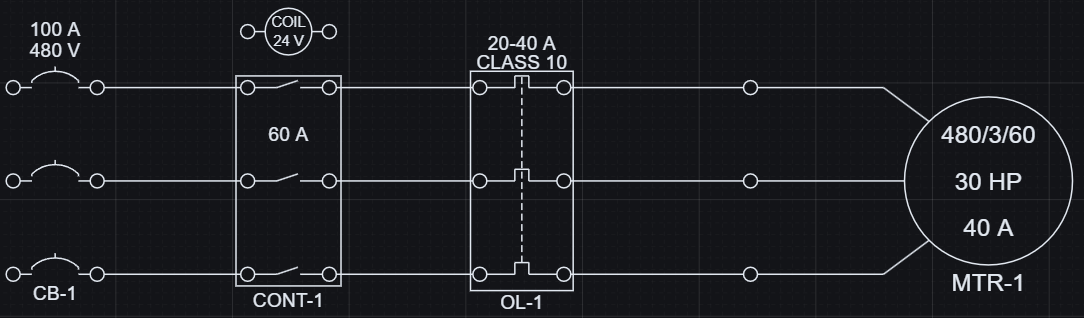
| 30 HP @ 480 V | 40 | 100 | 60 | 20-40 |
Geometry and data stay aligned because they are generated from the same logic.
Motor requirements resolve the coordinated starter components and the reported outputs together.
A lookup table maps motor horsepower and voltage to the required electrical components.
This keeps breaker, contactor, overload, and motor aligned as one system. Changing motor requirements updates the entire starter automatically.
Coordinated selections are reflected directly in the resolved starter outputs.
| Motor | FLC | Breaker | Contactor | Overload |
|---|---|---|---|---|
| 1 HP @ 240 V | 4.2 A | 15 A | 10 A | 5-10 A |
| 5 HP @ 240 V | 15.2 A | 40 A | 20 A | 10-20 A |
| 15 HP @ 480 V | 21.0 A | 60 A | 40 A | 20-40 A |
| 30 HP @ 480 V | 40.0 A | 100 A | 60 A | 20-40 A |
The resolved starter produces usable engineering data that can be exported and kept aligned with the schematic.
Motor, breaker, contactor, and overload values are available as generated data from the same evaluated starter.
Exported data stays aligned with the visible result, which keeps reporting and downstream review in sync with the design.
Generated data can be exported as CSV or JSON.
| Component | Role | Resolved output |
|---|---|---|
| Motor | Load | 5 HP, 240 V, 15.2 A |
| Contactor | Control | 20 A contactor, 24 V coil |
| Circuit Breaker | Protection | 40 A, 3-pole, 240 V |
| Overload | Protection | 10-20 A range, class 10 |
Motor starter sizing is a coordination problem. One change should update the whole starter definition consistently.
Open the example, change horsepower or voltage, and review the updated result.