Inputs
- Primary voltage
- Control voltage
- Control load
Input control load and voltage to automatically generate transformer and fuse sizing.
Enter inputs to automatically resolve transformer size, calculated currents, fuse protection, and generated data.
This sizing result is generated directly from the same logic used in the workspace.
Change load or voltage and the sizing updates automatically.
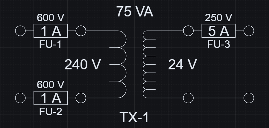
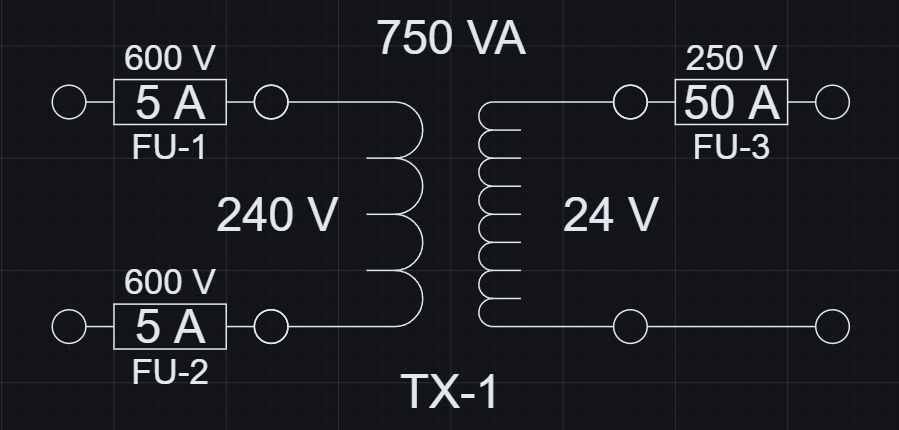
Increasing load steps transformer size from 75 VA to 750 VA and scales fuse protection automatically.
These changes are reflected directly in structured output data.
| Control Load (VA) | Transformer (VA) | Primary Fuse (A) | Secondary Fuse (A) |
|---|---|---|---|
| 50 | 75 | 1 | 5 |
| 500 | 750 | 5 | 50 |
Geometry and data stay aligned because they are generated from the same logic.
Control load and voltage resolve the transformer selection, calculated currents, and protection values together.
The sizing logic follows standard electrical calculations, encoded directly in the model.
The example uses standard fuse sizes of 1, 2, 3, 5, 10, 15, 20, 30, and 50 A. Fuse protection is selected by rounding each calculated current up to the next available standard rating.
Because the calculations are encoded directly in the model, the transformer symbol and both fuse symbols stay aligned with the resolved values without extra manual checking.
The resolved transformer produces usable engineering data that can be exported and kept aligned with the visible sizing result.
Required VA, transformer size, currents, and fuse values are available as generated data from the same evaluated model.
Exported data stays aligned with the schematic, so schedules and downstream checks can use the same resolved values.
| Required VA | 62.5 |
|---|---|
| Transformer Size (VA) | 75 |
| Primary Current (A) | 0.31 |
| Secondary Current (A) | 3.13 |
| Primary Fuse (A) | 1 |
| Secondary Fuse (A) | 5 |
Transformer sizing is repetitive work. Encoding it once keeps the calculation, the schematic, and the generated data aligned.
Open the example, change load or voltage, and review the updated result.